A few years back we worked on a site near the Oakland Estuary where an old warehouse had been demolished. The client planned a four-story residential building, but the top six feet were loose demolition debris mixed with bay mud. Standard shallow foundations would have settled unevenly. That project taught us how critical dynamic compaction design is for Oakland’s reclaimed and filled lands. We started by running a [MASW survey](/masw-vs30/) to map the velocity profile across the lot, then correlated the results with SPT borings to define target depths. The tamper weight and drop height were calculated so the energy reached the competent silt layer at 25 feet without over-compacting the upper fill. The whole process took three days and saved months of deep foundation work.
For Oakland’s variable fill depths, dynamic compaction design must match tamper energy to the loose layer thickness measured by prior geophysics.
Approach and scope
- SPT borings every 30 feet to check N-values against design target
- Density cone tests at random points to confirm uniformity
- Settlement monitoring plates installed before and after compaction
Site-specific factors
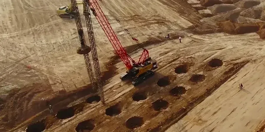
Oakland’s urban infill boom has pushed development onto old rail yards, industrial brownfields, and filled marshes. Many of these sites contain heterogeneous debris layers that can hide voids or soft pockets. If the dynamic compaction design ignores these lateral variations, the tamper might create a false compaction bulb that looks good on paper but leaves uncompressed zones under future footings. A contractor we worked with near Jack London Square found that a single-pass design left a 6-foot-wide soft spot under a load-bearing wall. We now require a pre-treatment geophysical survey to map anomalies before setting the energy parameters. That extra step costs a fraction of a structural repair.
Relevant standards
IBC 2021 Chapter 18 (soil compaction and improvement), ASCE 7-22 site classification for seismic design, ASTM D1586-18 for SPT verification, FHWA DTFH61-06-R-00117 guidelines for dynamic compaction
Related technical services
Pre-treatment geophysical survey
We run MASW and microtremor arrays to map fill thickness and identify anomalies before setting tamper parameters. This avoids wasted energy on zones that won’t densify.
Energy pattern optimization
Based on soil type and groundwater depth, we calculate drop height, tamper weight, and grid spacing to achieve the target relative density without over-compacting or damaging adjacent structures.
Post-treatment verification program
We perform SPT borings, CPT soundings, and settlement plate monitoring at intervals defined by the design to confirm that the compaction meets the project’s bearing and settlement criteria.
Typical parameters
FAQ
How does dynamic compaction design differ for Oakland’s bay mud compared to alluvial soils?
Bay mud is soft and saturated, so the impact energy dissipates faster. We use heavier tampers (20–25 tons) and tighter grid spacing (10–12 ft) compared to the looser patterns used on alluvial fans. Verification SPT N-values after treatment typically need to reach 15–25 blows per foot, whereas alluvial sites often target 10–15.
What is the typical cost range for a dynamic compaction design project in Oakland?
For a standard urban infill site with 15–20 feet of fill, the design and verification program runs between US$1.210 and US$3.810. The final cost depends on lot size, number of passes, and whether you need pre-treatment geophysics.
Can dynamic compaction design be used on sites with buried utilities or old foundations?
Only if those features are mapped and removed first. The tamper impact can fracture buried pipes or shift old concrete slabs. We require a GPR or utility locate survey before setting the drop pattern. If obstructions remain, we recommend excavation and replacement instead of dynamic compaction.
How long does the dynamic compaction process take for a typical Oakland lot?
A 10,000-square-foot lot with 15 feet of fill usually takes 3–5 working days for the compaction passes, plus 2 days for pre- and post-treatment testing. The design phase takes another 2–3 days, so the full cycle is about 10 business days.